Innovations depend on electronics, which is also a key enabler of global trends including connection, electric transportation, and renewable energy sources. These applications demand greater performance and dependability of electronic modules.
Its assembly includes extremely diverse process chains, including cutting-edge reel-to-reel organic form of electronic printing, robust and powerful power electronic connectivity techniques, and remarkably diminutive and productive SMT technology.
After briefly highlighting the massive global economic effect of the electronic modules, this article provides the latest developments in the field of electronic module assembly encompassing electronic components, substrate materials, assembly and packaging procedures as well as reliability and quality test procedures.
What Does an Electronic Module Mean?

Electronic modules combine all of the transmission control’s electronics components into a single unit. With respect to the transmission’s input torque, the engine speed, and speed of a vehicle having automatic transmission, the control unit for integrated transmission manages those hydraulic valves that are in charge of gear selection. It also provides a wide range of diagnostic capabilities.
- High reliability level because of the decreased component count
- Reduced weight for the automatic transmissions due to the incorporation of electronic components to a single module
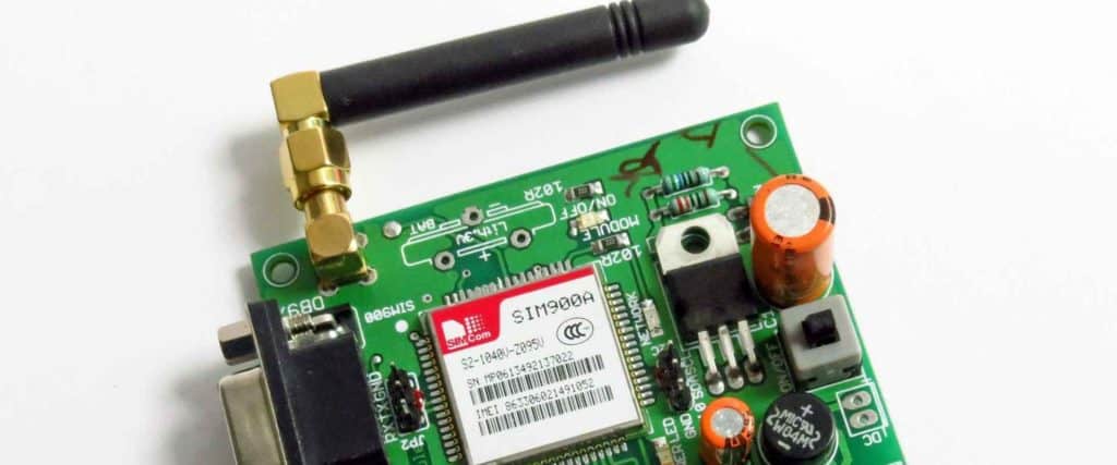
These electronic modules comprises of an integrated control unit for transmission and many sensors for position, speed, as well as pressure, coupled with connectors that helps in attaching into hydraulic valves. This control unit, connector, and sensors, are connected using lead frames. This electrical connection is formed via incredibly robust wielded form of connections.
There are various variations of electronic modules available: For the automatic transmission forms, the EM-L can be described as the mechatronic module. There are built-in sensors for temperature, location, and speed. The hermetically sealed housing houses its control unit for transmission. Wiring for modules is done on the lead frame. Sensors for pressure, location, and speed are built into the EM-P.
A circuit board with high temperature is utilized for the mounting as well as wiring of a module, allowing for the incorporation of numerous functions. The control unit for transmission is integrated into the molded case, which minimizes its design height. The actuator driving the electric oil pump is also available from the EM-P.
What is the Significance of the Electronic Module Assembly?
For a number of significant and quickly expanding markets, electronic module assembly can be viewed as the primary production technology as well as innovation driver. Consumer electronics are becoming lighter and smaller, more powerful, and far less expensive.
Examples include tablets and laptop computers, Cellphones, and wearables. Because of remarkable advancements in the semiconductor component, connector, assembly technologies, electric applications, i.e drives, converters, including controllers, become more powerful, dependable, and efficient.
Techniques for Electronic Module Assembly
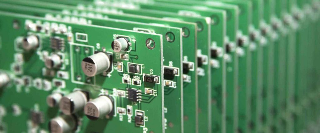
Depending on how the electronic components are used, electronic module assembly methods vary. Consequently, THDs are constructed using THT process chains, SMDs using SMT, whereas bare, unhoused, dies are attached to a circuit carrier using specific connectivity procedures.
A PCB must have metalized through-holes that have a diameter bit higher than the circumference of the pin in order to support THD assembly. The pins were also put into them during this mounting process.
Reliability and quality
The quality and dependability of electronic assembly are two characteristics that are closely related. Reliability determines if the functional characteristics will still be met even after a specific amount of mission time, whereas quality denotes the satisfaction of defined properties. After fabrication, quality is assessed using discrete metrics which are dependent on binary judgments, such as defects for every million parts, or through the dispersion of quality attributes with relation to permissible limits.
Components and Functions of Electronic Module Assembly
The desired functions must be decided upon before choosing a module. A module could have between two and five attributes. These are power outlet or inlet, filter, circuit protection, and/or the voltage selector.
With a detachable chord set, the power inlet seems to be in charge of supplying the device with electricity. The IEC 60320 C14 is the most popular intake, while some manufacturers also occasionally offer the C8, C6, and C20. Modules with a C14 inlet were typically designed for applications that have 10A and lower.
Outlet
The outlet can be described as an IEC 60320 connecting item that gives users the ability to draw electricity from any power supply. 10-20 amp outlets are available.
Switch
This is employed for turning on and off the power from the module towards the remainder of the device. The “” marking seen on a module must be vertical whenever attached. Module manufacturers prefer rocker-style switches.
Some modules employ a single-throw, double-pole switch, whereas others employ a single-throw single-pole switch. Although unlighted switches seem to be more typical, they can also be lit.
Circuit Protection
A fuse or circuit breaker is used for circuit protection. Both offer current protection for the equipment, lowering the chance that the short circuit will cause damage or endanger the user.
A fuse provides a benefit over the circuit breaker whenever a new product is designed for numerous markets due to being less expensive and simpler to modify. Fuse sizes can also be adjusted to the needs of the application, allowing one module to serve numerous purposes. Circuit breakers fitted in modules, meanwhile, are restricted by the rating and size of a breaker.
Fuses additionally possess multiple cleaning properties that enable further application customization.
Fuse carriers and holders are frequently included into modules for protecting the circuits from anomalous overloads and surges. The fuse’s amp rating shouldn’t be higher than the module’s total rating when establishing its amp rating.
In accordance with the application, the majority of modules having fusing capabilities must be defined as either double or single-fuse. Certain ones may be set either way.
Fuse orders must be placed separately because modules are excluded from them due to liability reasons. The appropriate fuse for such application must be chosen and ordered by the equipment maker for optimum efficiency.
Filter
A filter is a crucial component in equipment design, particularly in medical and high frequency applications.
It may eliminate certain Radio Frequency as well as Electromagnetic Interference which interfere with device operation. The filter aids in supplying the machinery with pure electricity.
Capacitors and inductors make up the circuit elements of filters. To reduce leakage current, capacitors in-between these circuit conductors were eliminated in medical versions of filters, as opposed to normal filters. This is significant for equipment whereby safety requirements strictly regulate leakage values of current to ensure patient safety.
Without or with a metal shield, Interpower filtered modules for power entry are often specified in the high-frequency applications. Radio and Electromagnetic frequency interference from of the equipment is removed by the RFI/EMI filter.
This avoids interference-related faults and stops the equipment from emitting noise that could interfere with the other equipment.
By supplying a module having a filter, a corporation must have samples for testing with their application to make sure they would work as expected. This is due to the fact that filter performance requirements are dependent on the industry standard of a test circuit of 50 ohm, and individual features of the design of an application may affect how well a filter functions whenever the coupling of circuits take place.
Voltage Selector
Equipment can be developed and produced to run on around 115 and 230 VAC thanks to voltage selection. By altering the transformer’s connections, the voltage selector modifies the voltage. The user can define the proper input voltage by altering the selection.
By rotating the fuse holder while removing it, voltage selection modifications can be accomplished. It is crucial to remember that voltage selector can be described as a special switch that operates in tandem with transformers built inside the equipment of the customer.
Although the transformer isn’t a physical component of the said module, it provides additional circuit routes for voltage selection procedure. The voltage selector isn’t really necessary when the customer does have a switched-mode electricity supply, which describes a power source between 90 and 264V.
Electronic Module Assembly Methods
First method
Curing a first mass that extends between the substrate assembly as well as the module housing whereas the substrate assembly’s circuit carrier is at least at an initial first temperature; curing the curable 2nd mass to form a better form of adhesive connection in-between the module housing’s side wall as well as substrate assembly; and cooling the circuit carriers down to less than a 2nd temperature less than the initial temperature after curing the first mass, where the circuit carrier is the substrate assembly.
When such electronic module assembly has been cooled below or equivalent to the 2nd temperature, this point of heat exchange layer is located at a 2nd distance out from the module housing’s lid, with a gap between the initial distance and 2nd distance of about 10 m.
The Second Method
This involves the introduction of the curable 1st mass between the module housing and substrate assembly, the module housing plunger being inwardly spaced from the housing’s side wall, the curable 1st mass extending from the plunger’s free end to the substrate assembly’s component.
Placing a curable 2nd mass away from the curable 1st mass in the space between its substrate assembly as well as the module housing’s side wall to ensure it extends out of this side wall into the substrate assembly’s circuit breaker
Heating its circuit carrier into the heated state, maintaining this same circuit carrier inside the heated condition for at least until this curable 1st mass reaches its cured state, bending this circuit carrier in a heated state to widen the gap in-between the plunger as well as the substrate assembly’s component, and bridging any gap with the curable 1st mass while its circuit carrier is being heated.
Explaining the Two Methods for Electronic Module Assembly
A technique for creating any electronic module assembly is one aspect. For that approach, the substrate assembly’s circuit carrier is heated to at least the first temperature while the curable 1st mass that extends between the two is cured. This curing of the curable 2nd mass creates the adhesive connection in-between the module housing’s side wall as well as the assembly of the substrate. This circuit carrier gets cooled down below to a 2nd temperature less than the initial first temperature after curing the 1st mass.
The electronic module assembly is another aspect. This electronic module assembly consists of the module housing, substrate assembly, as well as first mass that has been cured and extends between the two, as well as a surface for heat exchange formed through the circuit carrier surface that faces away from its cured 1st mass.
The surface point for heat exchange opposite that cured 1st mass has an initial distance from the module housing’s lid when the electronic module assembly has been heated to the general temperature of at least one 1st temperature, as well as a 2nd distance from this module housing lid when this electronic module assembly get’s cooled to the whole temperature that is equal to or below a 2nd temperature less than the initial temperature.
Conclusion
Depending on how the electronic components are used, electronic module assembly methods vary. Consequently, THDs are constructed using THT process chains, SMDs using SMT, whereas bare, unhoused, dies are attached to a circuit carrier using specific connectivity procedures.
The circuit carrier holding at least one electronic component, such like one or even more semiconductor chips with integrated semiconductor switches, is typically included in the electronic modules. For instance, the power supply designed for the supply of an inverter and electronic modules could feature an inverter, supply of power for supplying the inductive loads like motors, as well as other electronic circuits.
The purpose of this circuit carrier is to transport as well as electrically connect these electronic parts. This electronic module might well be forced up against the heat sink so as to dissipate the heat caused by losses of power in those electronic components and more generally, inside the electronic circuit built upon that circuit carrier.


