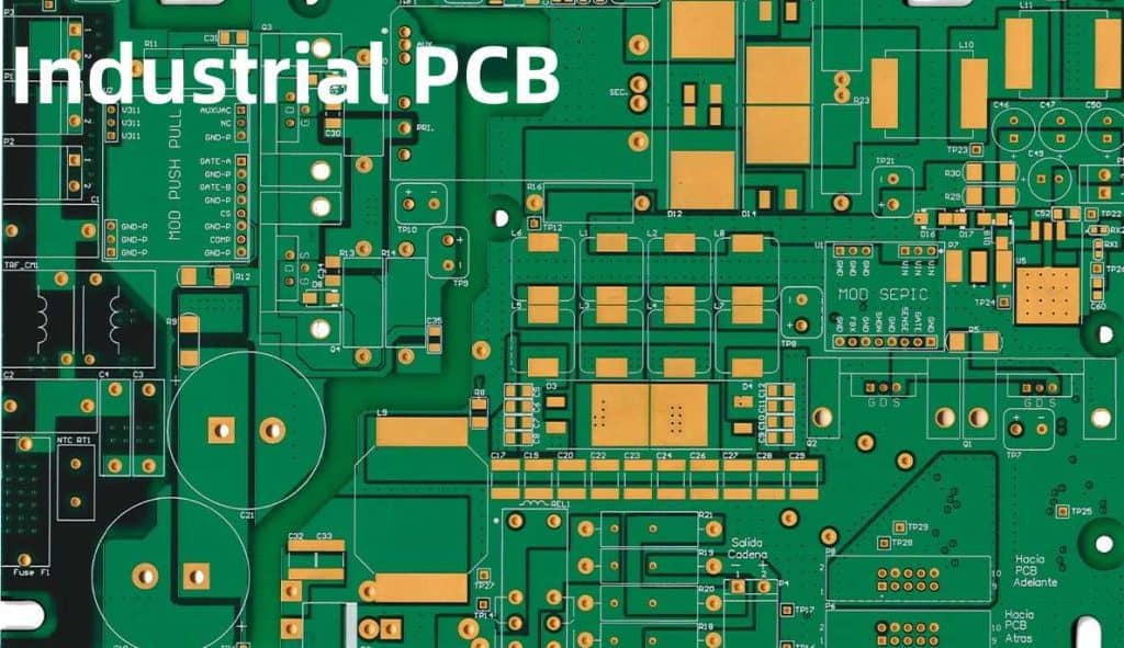
Industrial printed circuit boards (PCBs) refer to boards designed to operate reliably in demanding environmental conditions for extended time periods, usually 5-10+ years. They enable core functions for products used in sectors like transportation, energy, automation, aerospace and defense.
Unlike commercial grade boards, industrial PCBs face punishing temperature swings, shock, vibration, humidity and other challenges. They require rigorous design, component selection and testing well beyond typical electronics. In this guide, we explain what defines industrial PCBs and overview key design and manufacturing standards driving longer lasting, rugged boards.
Defining Industrial PCBs
Industrial PCBs differentiate on:
Operating Environments – Made for extreme industrial settings with wider temperature (-40°C to 105+°C), shock/vibration, humidity and other environmental demands.
Lifespan – Designed for high reliability over long product field life, often 10-15+ years of near continuous operations.
Criticality – High availability, functionality and safety criticality if the PCB fails. Whole industrial systems may rely on them.
Some examples of electronics using specially designed industrial class PCBs include:
- Motor drives
- Industrial controllers
- Power supplies
- Battery chargers
- Process transmitters
- Remote terminal units
- Railway electronics
- Downhole drilling tools
- Aerospace avionics
- Military vehicle electronics
Ruggedness, extended lifespan and high reliability distinguish industrial PCBs even though they may resemble commercial boards upon visual inspection. Their unique constraints lead to various design and manufacturing rules.
Industrial PCB Design Standards
Engineers designing industrial printed circuit boards face various international standards prescribing construction methods, documentation models, risk analysis techniques, testing procedures and key metrics to achieve longer field life over temperature extremes, vibrations and fast transients.
Some of the major standards include:
IPC Class 3
Issued under IPC-2221 standards, it covers generic performance requirements for industrial electronics printed boards especially related to:
- Temperature cycling (-65°C to 150°C)
- Vibration (10-500Hz at 10G+)
- Mechanical shock of 100-1500G
- Moisture resistance
- Other environmental stresses
Additionally covers recommended test methods, quality conformance criteria and inspection details useful for qualifying Class 3 boards. It represents a minimum level for most industrial applications.
IPC-6012 Automotive Electronics
Includes performance standards tailored for automotive/transportation use cases covering details like:
- Temperature ranges (-40°C to +125°C )
- Rapid humidity transitions
- Vibration profiles
- Test schedules
- Inspection criteria
- Qualification maintenance
Contains Class 1, 2, 3 acceptance levels (Class 3 most demanding)
IPC-A-610 Acceptability Standard
Visual defect criteria focused on workmanship, component orientation, soldering, part types and surface finishes. Used globally across PCB types to determine quality through manufacturing and acceptance inspection. All boards should pass IPC-A-610 for ship readiness.
IEC-61188 Circuit Boards
International guidelines from IEC on:
- Printed board layout and stackup
- Material/finish properties
- Electrical test methods
- Environmental stress testing
- Lot traceability through production
Of note for industrial boards are temperature/humidity cycling, mixed flowing gas corrosion testing and chemical resistance outlined.
UL 796 Standard for Printed-Wiring Boards
Underwriters Laboratory standard including various flame resistance, temperature indexing tests, electrical testing and constructions methods for boards.
Special UL 796 File Number recognition requires passing a range of safety focused design evaluations applicable to boards used in the UL safety certification ecosystem. Useful for boards used in end-products seeking UL listing especially for power electronics.
Industrial PCB Materials and Constructions
To withstand higher stress, industrial PCBs utilize additional materials and stackup methods:
Substrates
| Material | Properties | Applications |
|---|---|---|
| FR-4 Glass Epoxy | Low cost, moderate performance | Mild environments |
| High Tg FR-4 | Increased heat resistance | Power electronics |
| Polyimide | Extreme temperature range | Downhole, space, aviation |
| IMS | Thermal conductivity | LEDs, power devices |
| Ceramic | High frequency, temperature | RF/microwave, harsh |
| Metal Core | Heat dissipation | Power, LED |
Special Layers
- Extra thick copper (>2 oz.) for currents
- Impedance control layers
- Buried/blind vias for HDI
- Flood/plane layers for EMI shielding
- Graphite layers aid thermal heat spreading
- Double sided boards for shock/vibe damping
Coatings
- Conformal coating – moisture, contamination and corrosion resistance
- Potting compounds – vibration, thermal shock resistance
Edge Plating Connectors
Reinforced gold or tin-lead edge connector fingers withstand 10K+ mating cycles.
Industrial PCB Design Practices
Design is crucial for reliable functionality under demanding conditions:
Simulation Early – Extensive electrical, thermal, vibration modeling using tools like Ansys or Comsol to predict response and resonances. Spot problems ahead of building prototypes.
Derating Rules – Component derating guidelines lowering actual operating values below datasheet absolute maximums for voltage, current and power. Provides margin against parameter drift and lifespan reduction.
Redundancy – Extra backup pathways, traces, connections with automated failover capability. Prevents single points of failure.
Layout Methods – Thermal management techniques, stitching vias, edge control structures and wide, thick conductors to handle vibration, currents.
DFMx Analysis – Rigorous design analysis checks for manufacturability issues around thermal relief connections, trace widths, annular rings and more.
Standards Validation – Testing conformity with defense standards like MIL-PRF-31032 or those above helps qualify designs.
Getting board layout right from the start avoids costly re-spins later so taking the time to simulate, analyze and standard-proof industrial PCB designs is well worth it.
Industrial PCB Manufacturing and Testing
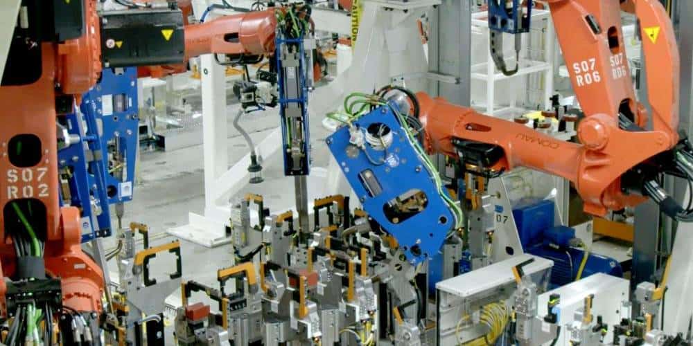
Producing industrial PCBs uses tighter process controls, auditing and qualification procedures than commercial boards:
Software – MES, ERP, MRP help coordinate workflow, Machine interfaces aid automated optical inspection and test
Fab – Cleanrooms, 6 sigma process controls on 35+ fabrication steps including pattern plating.
Test – ICT finds shorts and opens. Flying probe checks nodes. AOI inspects defects. X-ray confirms inner layer detail.
QA – Full traceability on materials and processes. Conflict minerals reporting required. Factory audited to AS9100, ISO 9001
Qualification – IPC Class 3 certification, UL E-file safety approval after verification testing during new product introduction and then sustained through periodic re-qualification
Personnel – Operators undergo certified training on accepting boards to IPC-A-610 visual standards reliably
Data Packs – Full archive packs for each board with photomicrographs, electrical test results,Corrective action reports from any issues detected during manufacturing or test
This combination of precision digital manufacturing technology paired with quality framework helps yield the reliable, long lasting circuit boards needed in industrial situations.
Choosing an Industrial PCB Partner
Given the unique demands of industrial PCBs, partner selection matters greatly:
Look for
- Years of experience specifically with industrial customers
- Wide material expertise like ceramic, IMS, flex-rigid and metal core PCBs
- Design for Excellence services aiding product development
- Staff engineers that can validate layouts to standards
- Global quality certifications – ISO, AS9100
Ask About
- Handling of proprietary customer data and red team reviews
- DFM optimization methods and GERBER analysis
- Standard testing and inspection processes
- Qualification reports provided
- Inventory and obsolescence management programs
- Counterfeit part avoidance controls
This best equips product teams to accelerate robust, compliant printed circuit board designs optimized to survive longterm in the real world conditions faced.
Conclusion
Industrial electronics have special PCB reliability requirements well beyond commercial boards to perform properly for years across extreme environments and safety critical applications.
By designing to rigorous standards upfront through simulation, analysis, derating and redundancy while choosing a tightly controlled, certified PCB factory, companies can meet their customers’ expectations in the harshest use cases. The specialized materials, testing and qualification processes for industrial PCBs delivers confidence for successful field deployment.
Frequently Asked Questions
What are some example applications using industrial class PCBs?
Typical applications leveraging industrial printed circuit boards include transportation power systems, factory automation controllers, energy management products, remote telemetry units, military vehicle computing, aerospace avionics, downhole drilling tools, naval systems and similar electronics where high reliability over 5-15+ years is necessary.
How are industrial PCBs different than commercial PCBs?
Industrial PCBs differentiate by:
- Supporting wider operating temperatures (-65°C to +150°C)
- Longer field deployment lifetimes (10-20 years)
- Required survival through harsh vibration, shock, moisture conditions
- High availability and uptime (>99%)
- Rigorous product testing and qualification
- Precision manufacturing process controls
- Traceability documentation Which exceeds commercial PCB environmental and lifespan demands.
What are some ways engineers design industrial PCB layouts differently?
Design techniques used for industrial printed circuit boards include:
- Component derating below absolute maximum levels
- Thermal simulation using finite element models
- Redundant connections and pathways
- Vibration damping edge mount connectors
- Conformal coating for moisture protection
- Thicker power and ground traces
- Double sided boards to withstand shock
- Extensive DFM analysis before release
Why is FR-4 still commonly used if industrial PCBs face extreme temperatures?
While special substrates like polyimides and ceramics handle wider temperature swings, FR-4 laminates have evolved “high Tg” versions usable to 150°C+ along with lower cost and better fabricator familiarity. So FR-4 remains an option for many industrial applications not hitting extreme temps.
What certifications should we look for in an industrial PCB manufacturer?
Key quality certifications to require from a factory producing printed circuit boards destined for industrial products include:
- ISO-9001-2015 – Quality management systems
- AS-9100D/EN9100 – Aerospace standard with strict guidelines
- ANSI/ESD S20.20 – Control of electronics ESD hazards
- ISO 14001:2015 Environmental Management
- IATF 16949 – Automotive quality management
- ITAR registration – Required for defense/aerospace PCBs
- IPC validated – For fabrication to IPC standards
These demonstrate the necessary capabilities to manufacture reliable boards over years of field deployment.


