Introduction
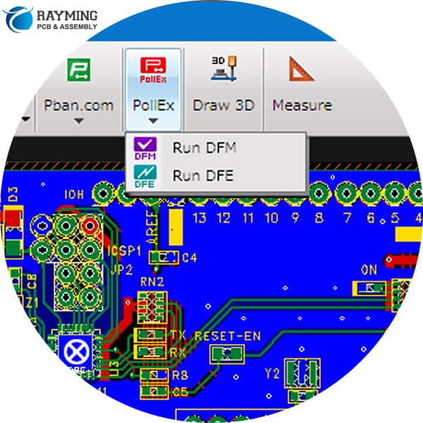
DFM stands for Design for Manufacturing. DFM check is the process of analyzing a product design to ensure it can be manufactured efficiently and cost-effectively.
With DFM analysis, engineers examine the design to identify and correct issues before releasing it to production. This avoids costly manufacturing problems down the line.
In this comprehensive guide, we will cover:
- The importance of DFM analysis
- When DFM checks should be performed
- The major areas analyzed in a DFM check
- Tolerances
- Clearances
- Draft angles
- Surface finishes
- and more
- DFM principles and guidelines
- Performing manual vs automated DFM checks
- Fixing DFM violations
- FAQs
By the end of this article, you will have a strong understanding of what DFM analysis entails and how it improves manufacturability. Let’s get started!
The Importance of DFM Analysis

DFM analysis provides enormous benefits for manufacturing by optimizing the design early on. Here are some key reasons DFM checks are critical:
- Saves money – It is far cheaper to fix issues in design stage rather than after production starts. DFM optimizes costs.
- Prevents defects – Flaws from a problematic design get replicated in every manufactured unit. DFM catches problems before they occur at scale.
- Avoids delays – A faulty design necessitates reworks and retrofits, stalling production. DFM prevents this wasted time.
- Improves quality – DFM facilitates higher assembly success, fewer scrapped parts, and consistent quality.
- Increases manufacturability – The design gets tailored to the capabilities of the manufacturing process.
For these reasons, leading engineering teams perform extensive DFM checks before releasing any product to the factory floor. The ROI from avoiding manufacturing issues is tremendous.
When Should DFM Analysis Be Performed?
DFM checks should be performed at multiple stages of the design process:
- Conceptual design phase – Early DFM analysis ensures the design direction inherently accounts for manufacturing best practices.
- Detailed design phase – Rigorous DFM checks should be conducted once the detailed design is frozen before release to production.
- Design revisions – DFM checks also needed whenever design changes are made to ensure no new issues are introduced.
In general, DFM checks should be an ongoing process throughout development rather than a one-time step at the end. Issues caught early in design iterations can prevent costly changes later down the line.
For complex products, DFM checks may be performed by a dedicated manufacturability engineering team. They take the designer’s CAD model and run intensive DFM analysis on it as a service.
No matter the design phase, integrating DFM as early and often as possible is key for optimizing manufacturability.
Major Areas Analyzed in a DFM Check
DFM analysis involves assessing the design from multiple aspects that impact manufacturing. Here are some of the major areas checked in a DFM review:
Tolerances
- Tolerance stackups calculated to ensure parts will fit together within specified range
- Tolerances not too tight for process capabilities
- Statistical tolerance analysis conducted where possible
Clearances
- Sufficient clearances between components for material thickness
- Adequate clearances to access assemblies and fasteners
- Clearances checked for operation without interference
- Minimum electrical clearances met
Draft Angles
- Draft angles added on vertical faces to ease ejection from molds
- Uniform draft angle between adjacent faces
- Adequate draft for deep/high parts and materials used
Hole Sizes
- Hole diameters meet tap drill sizes for specified thread types
- Hole sizes account for plating tolerances if plated
- Large holes have web thicknesses for required strength
Surface Finishes
- Appropriate surface finish specs for functional needs
- Finishes avoid tight textures causing friction or galling
- Radius surface finishes specified where needed
Heat Sinks
- Heat sinks sized properly for heat load and air flow
- Thermal interface material thickness considered
- Fins aligned with air flow direction
Welds
- Weld types appropriate for materials and joint design
- Gaps provided for welding access
- Distortion from weld process and sequencing minimized
Part Symmetry
- Parts designed symmetric where possible to avoid orientation concerns
- Non-symmetric parts clearly identified in drawings
Stamping and Forming
- Draw depths and minimum radii suitable for material thickness
- Bend radiuses checked for sheet metal parts
- Stamping web widths adequate for strength
Molding
- Draft angles provided on molded parts
- Radii added to corners to ease fill
- Core pins accessible and adequate for details
- Undercuts eliminated unless using collapsible cores
Casting
- Casting draft present with proper direction
- Minimum thicknesses to avoid porosity observed
- Appropriate finish allowances specified
Fastening and Joining
- Fastener sizes appropriate for materials and assemblies
- Fastener spacings meet engineering requirements
- Adhesives and press fits designed for required strength
Part Handling
- Points identified for safe automated part handling
- Low friction surfaces checked where automated sliding occurs
- Weight limits observed for manual lifting and ergonomics
Assembly Sequence
- Efficient tabs snap features used where helpful
- Conditional assembly sequences enabled where needed
- Assembly performed from stable datum points first
Test and Inspection
- Test points provided to verify full assembly
- Key dimensions defined for in-process inspection
- Go/no-go assembly checks incorporated
This covers some of the major areas scrutinized during a thorough DFM analysis. The full scope depends on the specific design and manufacturing process.
Key DFM Principles and Guidelines

While checking the above details, DFM engineers are guided by fundamental DFM principles that influence the overall manufacturability of a design:
Simple and Intuitive
- Design should be as simple as possible while still meeting functional needs
- Avoid unnecessary complex geometries and mechanisms
- Intuitive assemblies are easier to manufacture correctly
Error Proofing
- Incorporate go/no-go checks to prevent incorrect assembly
- Include guides, keys, and asymmetry for foolproof assembly
- Eliminate ways to assemble incorrectly through smart design
Standardization
- Maximize use of standard parts, materials, processes
- Follow industry and in-house standards where possible
Process Capabilities
- Stay within known process capabilities -avoid pushing limits
- Account for inherent process variation in tolerances
Modularity
- Break complex designs into self-contained modules
- Standard interfaces between modules for flexibility
- Modules can be made and tested independently
Consolidation
- Combine parts into single parts where possible
- Avoid unnecessary joints/fasteners to consolidate
Handling
- Design parts to be easily handled and positioned
- Add fiducials and other features to assist automation
Service and Repair
- Enable access to lifecycle maintainable components
- Fasteners, connectors, etc. designed for serviceability
By adhering to DFM principles like these, engineers can design products with manufacturing in mind right from the start. This flows into all the detailed checks conducted later.
Performing Manual vs Automated DFM Checks
DFM analysis is traditionally conducted manually by experienced engineers trained in manufacturing processes. However, automated DFM checking software has also emerged to supplement manual review.
Manual DFM Checking
With manual DFM analysis, engineers use their expertise to:
- Visually inspect CAD models for issues using a checklist
- Calculate key dimensions, stacks, and clearances by hand
- Simulate assembly sequences to validate manufacturability
- Judge surface finishes, drafts, radiuses by sight
- Suggest design changes to fix found issues
Manual checking taps into an engineer’s manufacturing knowledge. But it can be tedious and prone to human error.
Automated DFM Checking
DFM software automatically checks models for common issues like:
- Insufficient draft angles on faces
- Tight component clearances
- Hole dimensioning errors
- Thickness and radius violations
- Interference detection
- Standard violation checking
Automated tools provide consistent, rapid analysis. But software cannot fully replace an engineer’s judgement and insight yet.
In practice, the two methods are combined – engineers first run an automated DFM analysis then manually review the flagged issues. This gives the best results.
Fixing DFM Violations
When issues are identified from DFM checks, the designer needs to modify the CAD model to address them. Here are typical ways DFM violations are fixed:
- Relaxing tolerances – Increase tolerance windows to viable ranges
- Changing dimensions – Resize parts and geometry to meet requirements
- Adding draft – Add or increase draft angles where lacking
- Altering surface finishes – Change surface specs to better finishes
- Revising hole features – Modify hole sizes to suit tap sizes or add webbing
- Adding clearance – Provide adequate clearance between components
- Eliminating undercuts – Remove undercuts in molded parts through design changes
- Changing joinery – Revise joints, fasteners to improve assemble-ability
- Simplifying geometry – Simplify complex shapes to the basic functional geometry
- Separating parts – Break convoluted parts into simpler individual parts
- Refining assembly sequence – Optimize assembly steps for efficiency and clarity
Usually, many small changes are required versus one major redesign. The designer iterates to incrementally improve the design based on the DFM feedback.
Frequently Asked Questions
Here are some common questions that arise regarding DFM analysis:
Q: When should DFM analysis be done – by designers or by manufacturing engineers?
A: DFM principles should first be applied during the initial design phase. Later extensive DFM checks can be done by manufacturing engineers as an independent quality check.
Q: What are some limitations of automated DFM analysis tools?
A: Automated tools miss context-specific issues and have limited capability to suggest fixes. But they rapidly find basic issues like insufficient drafts.
Q: How is DFM analysis different for machined parts versus plastic injection molded components?
A: Each process has unique DFM considerations – for machining, avoid thin walls, deep pockets, and surfaces hard to reach with cutters. For molding, check drafts, radii, tolerances.
Q: What is the right level of detail for a DFM analysis?
A: It depends on the design complexity, production volume, cost, lead time, and other factors. Higher volume or cost products warrant extremely exhaustive DFM review.
Q: Is DFM analysis applicable beyond mechanical and physical product design?
A: Yes, the principles of optimizing a design for ease of execution extend to many fields. DFM concepts are relevant even in UX design, process design, and more.
Conclusion
DFM analysis is a critical step in optimizing a product design for manufacturing and assembly. By thoroughly checking key areas like tolerances, clearances, surface finishes, and reviewing the design from a manufacturing perspective, engineers can catch and correct issues early.
Performing DFM checks systematically at each stage of design, incorporating both automated tools and manual review by experienced engineers, results in the highest quality analysis. The ROI from avoiding manufacturing problems is well worth the effort invested into rigorous DFM practices.
With the methodology and best practices covered in this guide, you now have strong knowledge of what an effective DFM analysis entails. Leverage DFM practices in your organization to save costs, reduce defects, shorten time-to-market, and ultimately create products optimized for manufacture.
Free of Cost DFM Check
DFM (Design for Manufacturing ) is known as file check and it is basically an added value service that most of PCB manufacturers offer. The services of DFM are related to the checking of PCB design for any possibility of issues which may hinder the process of PCB manufacturing and fabrication. In case if any issues are sorted, customers are got in touch on immediate basis and issues are resolved at higher priority and fabrication of PCBs is arranged accordingly.
The DFM check offered by RayPCB is cost-effective of the system we use for DFM check is an autonomous way for enabling the manufacturing and fabrication system of PCBs hassle-free and sort out issues which cause trouble. The autonomous system of FDA check is known as Valor DFM. The system helps in lowering cost of PCB and saves time as well. The DFM is conducted on the basis of five aspects at RayPCB known as single layer and mixed layer checks, silkscreen checks, drill checks, and ground/power checks. The details are given below.
1. Drill Checks:
The action of drill checks is for finding out the potential defects which may hinder the manufacturing process in different layers of PCB. Statistics are generated on drill layers. The drill checks is supposed to be operated on drill layers only. It is using drill stack, bottom and top layers along with ground or power layer in stack. The checklists are given below.
| Items | Functionalities |
| Ground/Power Shorts | It reports the drills which are touching copper nets of more than ground or power layer. |
| NPTH to Route | It reports the drills which are having mounting or tool hole and NPTHs which are very close to path. |
| Missing Holes | It reports the holes which are missing drills. |
| Hole Size | It offers list of vias, NPTHs, and PTHs which required drills. |
| Extra Holes | It reports the extra holes which are redundant and are not belonging to any of the Pads. |
| Hole separation | It reports the extra holes or duplicate holes or the holes which are closed. |
| Thermal Connection | It reports the absence of thermals for pin drills and calculates the approximated copper area for each thermal connection via mixed and ground layers. |
| Stubbed Vias | It reports the vias which are not connected to two or more copper layers. |
2. Mixed and Single Layered Checks:
The mixed and single layered checks is designed for finding potential manufacturing defects and generation of statistics in mixed and single layers. The action is dedicated for single layers, however it can also be implemented on mixed and other layers. The main checklist are given below.
| Items | Functionalities |
| Size | It has information of the size of pads, text, arcs, line neck downs, vias, shaved arcs, and shaved lines. |
| Stubs | It has information of endpoints of unconnected lines. |
| Spacing | It has information of the violations among nets and circuits of pads among text, shorts, and spacing among CAD nets and non-touching features of CAD. |
| Silver | It has information of the silver lines among pads and lines. |
| Route | It has reports of the displacement violations among pads and edge of route. |
| Drill | It has information of the displacement among vias, NPTHs, PTHs, Pads, rings, Circuits, and copper etc. |
3. The Ground/Power Checks:
The intentions of the ground/power checks is to have an identification of the manufacturing defects in ground and power in mixed layers. It has utilization of various algorithms for diagnosis of positive and negative power along with ground layer. Checklist is given as follow.
| Items | Functionalities |
| Route | It has report of the closed spacing among route and copper features. |
| NFP Spacing | It has information of spacing among NFP-planes, and NFP-NFP. |
| Drill | It has information of distance violations among vias to plane, annular rings, clearance, and copper etc. |
| Plane Spacing | It has information of spacing among various features of planes. |
| Thermal | It has information of spoke reduction and width of the connectivity of thermal pads. |
| Plane Width | It has reports of inadequate width of the layer of copper among 2 drills which are connected on copper plane. |
| Keepout Areas | It has information of features of outside and inside as well as keepout and keepin areas. |
| Plane Connection | It has reporting of the detached areas of copper which are utilized as reference planes and are in design which are causing unreferenced net or missing electrical connection. |

4. The Solder Mask Checks:
This function is for checking layers of solder masks for any potential manufacturing defects. The layers of solder masks are considered negative and the positive features are describing clearance of the solder masks. The function is also checking the solder paste which is deposited on the pads. This function is operating on single layer solder mask and below is its major checklist.
| Items | Functionalities |
| Spacing | It has information of the spacing among clearance. |
| Extra | It has a reporting of soldering mask features which are lacking copper pads and are not intersecting each other. |
| Drill | It has reporting of close distant to solder mask opening of NPTH annular rings. |
| Bridge | It has information of pads which are there without solder mask. |
| Silver | It has reports of the silvers among clearance and solder mask. |
| Missing | It has reports of the missing clearances. |
| Coverage | It has information of lines which are too close to clearance. |
| Pads | It has reports of the opening of distance to solder mask of pads comprising of undrilled pads. It has information of special group as well such as gaskets, information of width of solder mask etc. |
5. The Silkscreen Checks:
This function has an intention of finding potential manufacturing defects present in layers of silkscreen and also generation of statistics. This function is only used for checking silk screen layers because it has a reliance on job matrix related to external copper, layers of drills and solder mask. Below are details of checklist.
| Items | Functionalities |
| String Overlap | It has information of intersection or touching of silkscreen with various string values. |
| SMD Clearance | It has information about spacing among SMD pads and silkscreen features. |
| Pad Clearance | It has reports of spacing among pads and silkscreen features. |
| Solder Mask Clearance | It has information of spacing among clearance of solder mask and silkscreen features. |
| Hole Clearance | It has information of spacing among drills and silkscreen features. |
| Line Width | It has information of the violations of width and length to its respective ratio. |
| Route Clearance | It has information of spacing among route features and silkscreen features. |
You can avail advantage of DFM free check offered by RayPCB right away. Don’t waste time and contact us right now for availing this amazing deal of free DFM check.
More PCB Design guides :


